Requirements, principles, and structures of mechanical stirred fermentation tanks
Basic requirements for Bioreactor Fermenter
Fermentation tanks should have a suitable aspect ratio. The ratio of height to diameter is generally (1.7-4): 1. The larger the height to diameter ratio, the better the dissolved oxygen effect and the higher the oxygen utilization rate. It should be noted that the larger the aspect ratio, the higher the tank, which affects the construction cost.
The fermentation tank should have a suitable design pressure. At present, the design pressure of most fermentation tanks is 0.3 MPa, and the working pressure is below 0.15 MPa.
The Stirrers and its internal structure facilitate the dissolution of oxygen. Fermentation tank Stirrers blades are generally a combination of multiple Stirrers blades to achieve the best dissolved oxygen effect. The internal baffle and vertical tube structure of the fermentation tank create turbulence in the culture medium during stirring, increasing the stirring effect.
The fermentation tank should have good sealing. Fermentation tanks require high sealing requirements, especially for mixing seals. All interfaces and mechanical seals must meet sealing requirements to minimize leakage and reduce the probability of bacterial contamination during cultivation.
When designing the interior of the fermentation tank, it is necessary to avoid sterilization and mixing dead corners. Prioritize simplicity and stability to prevent loosening of bolts inside the tank.
The fermentation tank should be easy to operate and clean. The inner surface is polished with a mirror finish to reduce the adhesion of culture medium and other materials. The interface adopts clamp quick connection methods for easy operation, cleaning, and maintenance.
The fermentation tank should have sufficient heat exchange area. When designing a fermentation tank, the heat exchange area should be calculated to ensure sufficient heat exchange surface for rapid heating and cooling, minimizing the damage of nutrient components in the culture medium during sterilization, and ensuring the accuracy of temperature control during fermentation.
Working principle of Bioreactor Fermenter
The mechanical stirring fermentation tank mainly utilizes the stirring and crushing effect of the mechanical stirring blade and the dispersing effect of the air distributor to disperse the sterile air into small bubbles that mix with the fermentation broth, promoting the dissolution of oxygen in the fermentation broth to ensure the oxygen required for microbial growth and product production.
The two basic indicators for measuring the quality of a fermentation tank are the dissolved oxygen coefficient (KLa) and the amount of power required to transfer 1kg of oxygen.
The fermentation tank maintains a certain pH of the fermentation broth by adding acid, alkali, etc;
Maintain a certain temperature of the fermentation broth by passing cooling water, hot water, steam, etc. through jackets, coils, serpentine tubes, etc;
Strict aseptic conditions are maintained during microbial fermentation through tank sterilization, sterilization filter filtration, sealing, and maintaining positive pressure inside the tank.
By controlling parameters such as ventilation rate, dissolved oxygen, stirring speed, tank pressure, pH, temperature, feeding, bacterial density, and exhaust gas detection, the fermentation is ensured to be in the optimal state.
Main structure of Bioreactor Fermenter
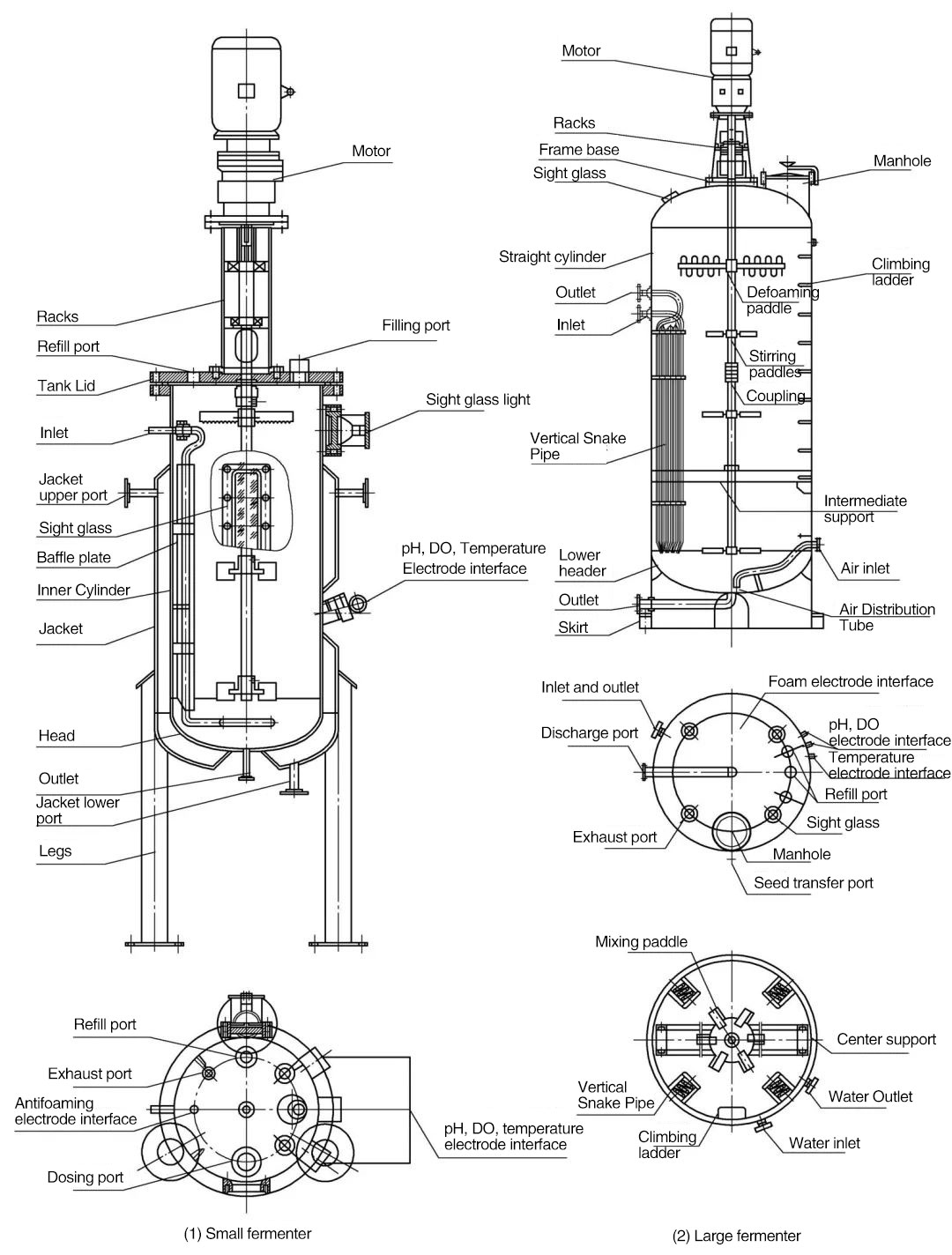
The main structure of a fermentation tank includes: tank body, Stirrers, baffle, air distribution device, mechanical seal, heat exchange device, sensor interface, accessory structure, etc., as shown in the figure.
(1) Tank body
The fermentation tank is composed of a cylindrical straight body and an elliptical or butterfly shaped upper and lower head connected together.
The nominal volume (lower head and cylinder volume) of the fermentation tank is 1m3 or less. The upper head and straight cylinder of the fermentation tank are connected by flanges and equipped with hand holes for feeding, cleaning, etc. If maintenance is required inside the fermentation tank, the upper head needs to be opened;
The head of the fermentation tank with a nominal capacity of 1m3 or more is directly welded to the tank body, and there is a manhole for feeding, cleaning, and tank maintenance.
On the top of the tank, there are interfaces such as manhole, feeding port, exhaust port, pressure gauge interface, inoculation port, etc.
Interfaces on the tank body: air inlet, seed transfer port, sampling port, discharge port, various sensor interfaces, circulating water inlet and outlet, etc.
The structure and main dimensions of commonly used mechanically ventilated stirred fermentation tanks have been standardized, and can be divided into various types based on the size and purpose of the fermentation tank. It is mainly divided into three levels: laboratory scale, pilot scale, and production scale.
There are 1, 3, 5, 10, 20, and 30L fermentation tanks in the laboratory scale;
The pilot scale includes 50100200300500L and 1,2,3m3 fermentation tanks;
There are fermentation tanks with production scales of 5, 10, 20, 50, 100, 200, and 200 cubic meters. (General classification, not absolute.)
We can choose the fermentation tank capacity according to our needs.
The geometric dimensions of the universal mechanical stirring and ventilation fermentation tank are shown in the following figure.
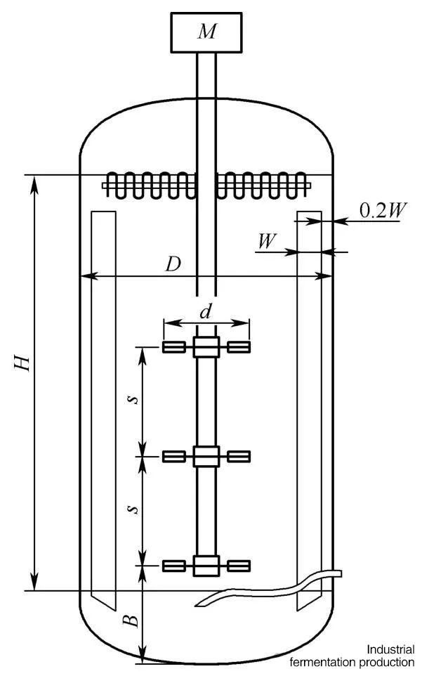
In the figure, H represents the height of the straight barrel of the fermentation tank, in meters;
D - fermentation tank diameter, m;
d - mixer diameter, m;
W - width of the baffle, m;
B - Distance between the lower mixer and the bottom of the tank, m;
s - spacing between mixers, m.
The geometric proportions of commonly used mechanical agitation and ventilation fermentation tanks:
H/D=1.7~3.5;
d/D=1/3~1/2;
W/D=1/2~1/8;

=1-2 (Below, 2 and 3 represent the number of baffles in the mixer)
The size of the fermentation tank can be described as full capacity and nominal capacity.
The full volume is the sum of the volume of the straight barrel and the volume of the upper and lower heads of the fermentation tank;
The nominal volume (V0) refers to the sum of the volume of the straight cylinder of the tank body (Va) and the volume of the lower head (Vb). Nowadays, the size of a fermentation tank is generally referred to as its full capacity.
The loading coefficient is the ratio of the liquid volume to the total volume of the fermentation tank, and generally the loading coefficient of the fermentation tank is 70% to 80%.
In the process of fermentation tank cultivation, if more foam is produced, the loading coefficient can be appropriately reduced;
For fermentation tanks with less foam and less aeration during the cultivation process, the charging coefficient can be appropriately increased.
(2) Blender
The main function of a mechanical mixer is to mix materials, crush bubbles, and enhance heat and mass transfer.
The mechanical stirrer keeps the solid materials in the fermentation broth suspended, thereby maintaining the mass transfer of the gas liquid solid three-phase mixture;
Disperse the incoming air into small bubbles and mix them evenly with the fermentation broth, increase the gas-liquid contact interface, improve the mass transfer rate between gas and liquid, and enhance dissolved oxygen;
By stirring, the temperature of each part of the fermentation tank is evenly distributed, enhancing the transfer of heat.
The Stirrers impeller generates axial flow, radial flow, and tangential flow during stirring.
Axial flow is the flow direction of the fluid parallel to the stirring shaft. The fluid is pushed down by the blades, and when it encounters the bottom of the container, it flips up to form an up and down circulation flow. The liquid circulation flow rate is large, as shown in Figure (1).
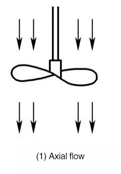
Axial flow causes the overall flow of liquid in the fermentation tank to form an axial circulation, which is conducive to macroscopic mixing, but the turbulence level is not high. The main types of propeller blades include paddle type and propeller type mixing blades.
Radial flow is the direction of fluid flow perpendicular to the stirring shaft, flowing along the radius of the fermentation tank between the stirrer and the inner wall. When it encounters the container wall, it splits into two streams of fluid that flow upward and downward respectively, and then returns to the blade end without passing through the blade, forming two circulation flows of upper and lower, as shown in Figure (2).
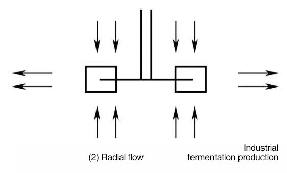
Radial flow makes the overall flow of liquid in the fermentation tank more complex, with a large shear effect on the liquid, which is beneficial for the breakage of bubbles, but can easily cause damage to microbial cells. The main blade forms include turbine type Stirrers blades.
Tangential flow refers to the rotational motion of fluid around an axis in a container without baffles. Under the action of centrifugal force, the fluid rushes towards the wall of the container, causing the liquid level in the central part to drop and form a large vortex, as shown in the following figure.
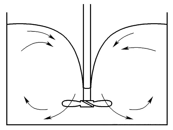
Mechanical stirring tangential flow
In severe cases, the Stirrers may not be fully immersed in the fermentation broth, resulting in a significant decrease in stirring power.
At present, the most commonly used type of fermentation tank is the turbine Stirrers, as shown in the figure below, which is divided into flat blade turbine Stirrers, curved blade turbine Stirrers, arrow blade turbine Stirrers, etc. The stirring blade is generally 6 pieces.

Turbine type Stirrers blade
(3) Barrier board
The function of the baffle is to change the direction of the fluid, from tangential flow to axial flow, to generate turbulence during stirring, prevent vortex formation, increase dissolved oxygen content, improve mass and heat transfer efficiency, and enhance stirring efficiency.
The upper part of the baffle should be above the liquid level, and the lower part should extend to the bottom of the tank, level with the head.
The width of the baffle is generally (0.1-0.12) D. (D is the diameter of the fermentation tank)
The installation of 4-6 baffles can meet the full baffle condition. The so-called "full baffle condition" refers to that when adding baffles and other accessories that can act as baffles in the fermentation tank, the mixing power remains unchanged and the vortex basically disappears.
The installation of the baffle has several characteristics:
There is a gap between the baffle and the tank wall, which can effectively prevent cleaning and sterilization dead corners between the tank wall and the baffle;
The baffle is detachable for easy maintenance;
The baffle is processed to bend in the direction of liquid flow at the outermost part, which can effectively increase the strength of the baffle and reduce the friction of the liquid on the outside of the baffle;
In fermentation tanks of 10m3 and above, tubes can replace baffles.
(4) Mechanical seal
In a mechanical stirring fermentation tank, except for magnetic stirring, which does not require the stirring shaft to be extended out of the fermentation tank, all others require the stirring shaft to be extended out of the fermentation tank and then rotated by a motor. At the part where the stirring shaft extends out of the tank body, a mechanical seal is required to prevent leakage.
Mechanical seals can be divided into stuffing box mechanical seals and end face mechanical seals. End face mechanical seals can be divided into single face mechanical seals and double face mechanical seals based on the number of sealing end faces.
The stuffing box mechanical seal is composed of stuffing box body, stuffing bottom liner, stuffing cover, and clamping bolt, as shown in the figure.
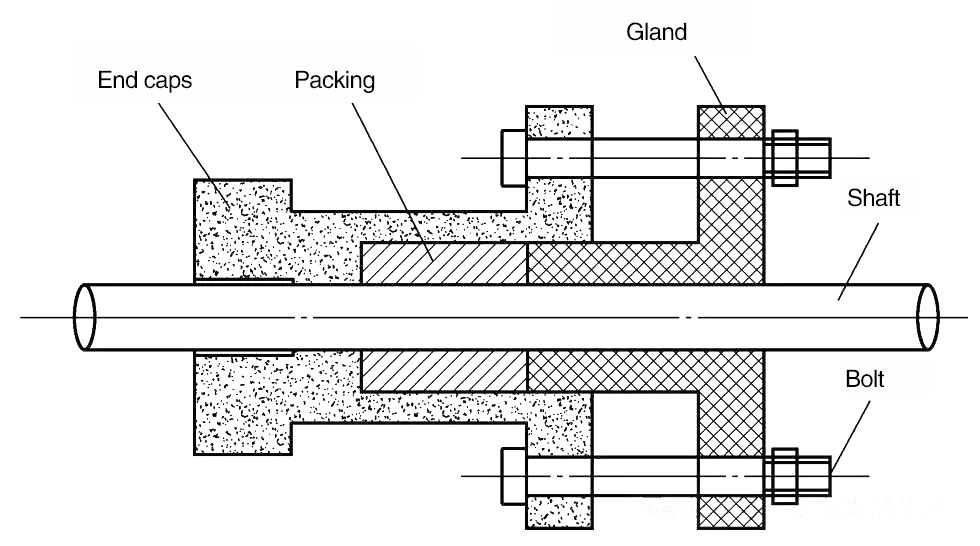
Stuffing box mechanical seal
Packing box is a method of adding packing material into the packing chamber, which is compressed by a cover and a tightening bolt to ensure tight contact between the packing material and the shaft, achieving the purpose of sealing.
The advantages of stuffing box mechanical seals are low price, simple structure, easy maintenance, low requirements for shaft machining accuracy, and minimal shaft wear.
The disadvantage is that there are many blind spots, making it difficult to completely sterilize; Short service life, large leakage, poor sealing effect, easy bacterial infection, frequent maintenance, and rarely used in fermentation tanks.
According to the temperature and pressure range of the fermentation tank, the most commonly used is the single end mechanical seal, as shown in the figure.
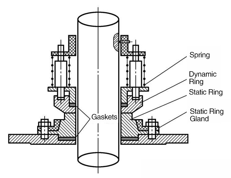
Commonly used single end mechanical seal structures
The end face of a single end mechanical seal is made of two materials with different hardness, namely the dynamic ring and the static ring.
The static ring is fixed on the fermentation tank, with a non rotating end face. It is tightly adhered to the mechanical seal base of the fermentation tank through a sealing gasket, ensuring that there is no leakage at the contact area between the static ring and the fermentation tank.
The dynamic ring is fitted onto the shaft, and there is a sealing gasket inside that tightly adheres to the shaft, which can prevent leakage between the dynamic ring and the shaft. The upper spring of the dynamic ring presses the dynamic ring towards the static ring, ensuring that the smooth end face of the dynamic ring is in close contact with the smooth end face of the static ring, achieving the purpose of sealing.
Single end mechanical seals need to be well protected before and after installation to ensure a smooth contact surface. During installation, try to avoid tilting the moving and stationary rings as much as possible.
Small mechanical seals are generally installed inside the tank, and for this type, mechanical seals with simple structure and few dead corners should be selected as much as possible; Larger mechanical seals are installed outside the fermentation tank, making them easy to fix, adjust, and maintain.
(5) Air distribution device
The main function of the air distribution device is to blow sterile air into the fermentation tank, dispersing the sterile air into small bubbles for more complete dissolution in the fermentation broth, which is beneficial for bacterial growth.
The commonly used forms of air distribution devices are single tube and annular tube, as shown in the figure.
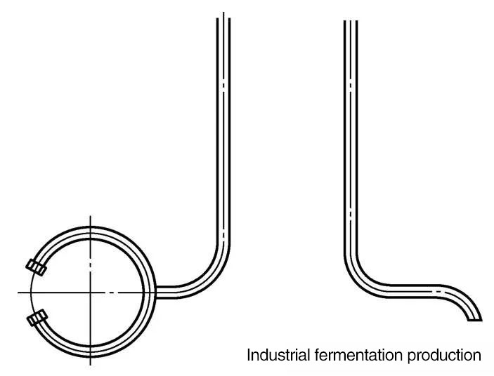
Circular tube and single tube air distributors
The single tube air pipe extends to the lower part of the mixing blade at the bottom, with the opening facing downwards, to ensure that there is no accumulation of materials or dead corners inside the pipe. At the same time, the air blowing downwards can blow up the material at the bottom of the tank, and the bubbles are further crushed by the mixing blade, which can achieve a good dissolved oxygen effect. The distance between the bottom of the air outlet and the bottom of the tank varies slightly depending on the size of the tank.
The annular tube type is welded at the tail of the air tube, and the annular tube is generally a closed circle or an open circle. There are some small holes at the bottom and sides of the annular tube, and the sum of the cross-sectional areas of all the small holes is approximately equal to the cross-sectional area of the intake pipe.
Circular tube distributors are generally used for fermentation tanks with smaller volumes. Smaller fermentation tanks are limited by their volume and height, resulting in shorter residence time of air in the fermentation broth. Therefore, using an air ring distributor to turn the air into smaller bubbles is beneficial for increasing dissolved oxygen. Single tube type is used for larger fermentation tanks.
(6) Heat exchange device
Fermentation tanks require sterilization and temperature control, which requires heat exchange devices. The heat exchange devices used for fermentation tanks mainly include jackets, coils, vertical coils, and vertical tubes.
Fermentation tanks with a volume of 5m3 or less generally use jackets, while tanks with a volume of 5m3 or more can use coils, vertical coils, or vertical tubes.
If the height of the upper part of the jacket exceeds the liquid level of the fermentation broth, no calculation is required. The jacket has imports and exports. During temperature control, cooling water or hot water enters from the lower position of the jacket and is discharged from the higher position, as shown in the figure;
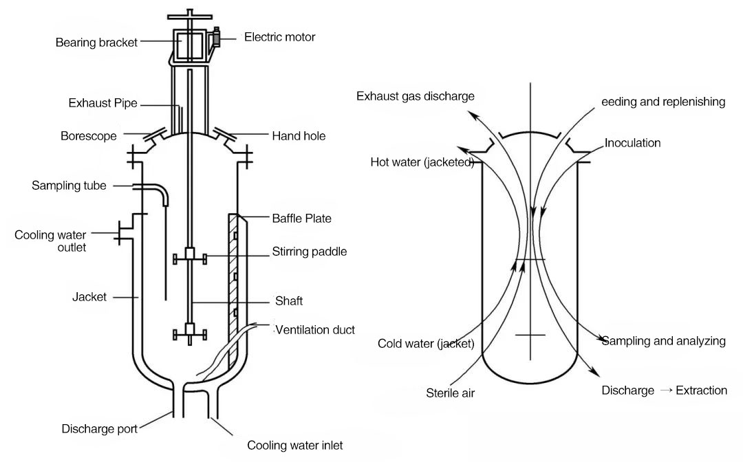
Jacket heat exchange device and heat exchange schematic diagram
During sterilization preheating, steam enters from the high position of the jacket and condensed water is discharged from the low position of the jacket.
Advantages of the jacket: simple structure and easy production; There is no cooling device inside the tank, which can effectively reduce dead corners and facilitate tank cleaning and sterilization.
The disadvantage is that the cooling water flow rate is low, the heat transfer is uneven, and the heat transfer efficiency during fermentation is relatively low.
Coil is a spiral stainless steel piping system inside a fermentation tank, with an inlet and outlet, and high heat transfer efficiency. As shown in Figure (1).
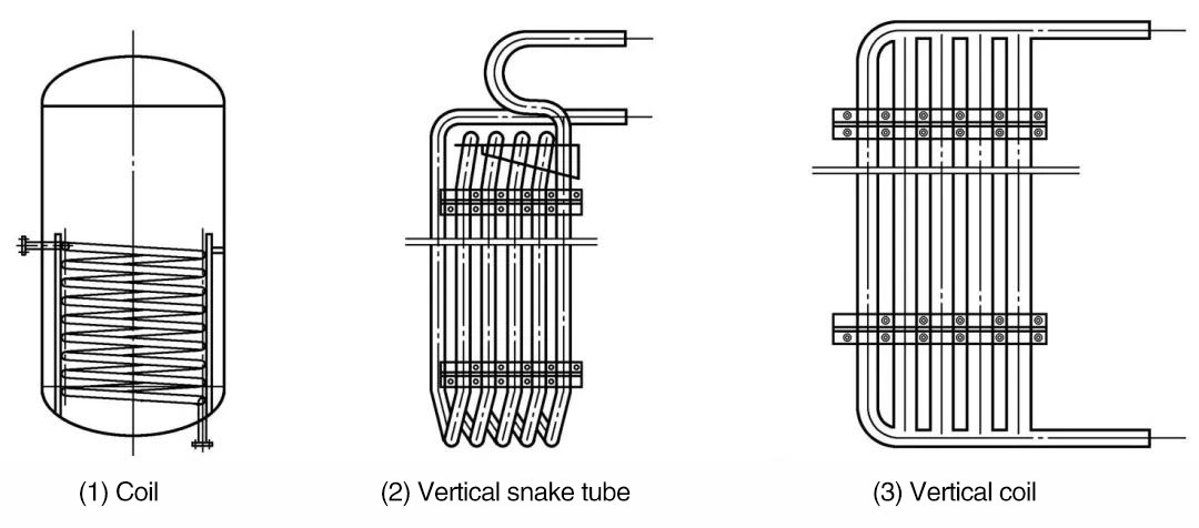
As shown in Figure (2), each set of vertical serpentine tubes in the fermentation tank is composed of many vertical stainless steel tubes. The stainless steel tubes are connected and welded in series through 180 ° elbows, ultimately forming a set of vertical serpentine tubes with one in and one out.
Generally, there are four, six, or eight groups, and the specific quantity and pipe diameter are determined according to the size of the tank body and heat transfer requirements.
Vertical coil has higher heat transfer efficiency, larger heat transfer area, and no short circuit problem in the heat transfer medium compared to jacket. And the snake tube has a high pressure resistance, which can use relatively high-pressure heat exchange media to improve heat transfer efficiency.
Vertical snake tubes can also serve as baffles, and there is no need to install baffles inside the fermentation tank.
However, the manufacturing of snake tube welding is relatively complex, with many welds and a relatively high probability of weld leakage, making it difficult to repair leaks.
As shown in Figure (3), each set of vertical tubes in the fermentation tank consists of multiple vertical stainless steel tubes, which are welded in parallel through an inlet pipe and a drain pipe, ultimately forming a set of vertical tubes with one inlet and one outlet.
The specific quantity and pipe diameter shall be determined according to the size of the tank body and heat transfer requirements.
Vertical tube processing is simple, but there is a short circuit problem with the heat transfer medium, resulting in lower heat transfer efficiency compared to vertical coil. Vertical snake tubes can also serve as baffles, and there is no need to install baffles inside the fermentation tank.
(7) Defoaming device
Because there are protein and other substances easy to foam in the fermentation liquid, more foam can be produced under the effect of ventilation and stirring during fermentation. Too much foam will be discharged from the exhaust port of the fermentation tank, causing liquid leakage, and increasing the probability of bacteria infection during fermentation.
The defoaming device of fermentation tank is a device to physically eliminate the foam generated during fermentation. At present, the main defoaming device is defoaming paddle. Due to the limited effectiveness of defoamers, many fermentation tanks have been cancelled
Defoamer blades are used to physically break up bubbles, mainly in the form of snakes, serrations, and rake teeth, as shown in the figure.
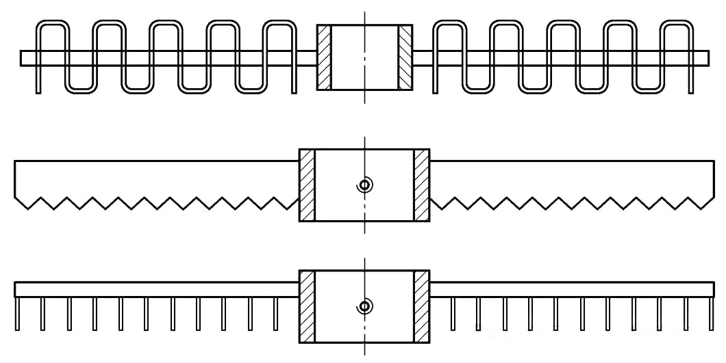
Common defoamers
The defoaming paddle is installed on the upper part of the mixing shaft and rotates with the mixing shaft. When the foam reaches the position of the defoaming paddle, the defoaming paddle can break the foam.
Summarize
With the development of biotechnology and the continuous growth of industrial fermentation demand, the design and application of mechanical stirring fermentation tanks are also constantly optimized and innovated.
At present, by precisely controlling key parameters in the fermentation process, such as pH, temperature, dissolved oxygen, stirring speed, etc., the metabolic efficiency of microorganisms and the yield of products can be significantly improved. These parameter controls have also become more stable and accurate with the development of online inspection equipment.
The structure of the fermentation tank will be customized according to the characteristics of the fermentation bacteria, combined with the principles and structure of the fermentation tank in this article, to meet our different fermentation conditions.
In addition, the automation and intelligent control system of the fermentation tank provides the possibility of achieving more precise process control, with parameter control by the central control system. Only the required air volume, temperature, pH, feeding speed, etc. need to be set and automatically controlled and adjusted by the system. These technologies further promote the modernization and efficiency of the fermentation process.